11 ways machine vision is used in electric vehicle battery production.

Here at IVS our vision system solutions are utilised for the inspection of electric vehicle battery production. We thought it would be interesting in this post to drill down a little more of how machine vision is used in this fast-developing industry sector.

How are electric vehicle batteries made?

Carbon or graphite, a metal oxide, and lithium salt are all used to make lithium-ion batteries for electric vehicles. Positive and negative electrodes are made up of these elements, which when mixed with electrolyte form an electric current that allows the battery to work to power a car. It’s also the same type of battery that’s used in common devices like cell phones and computers, but on a far larger scale.

The materials used to make EV batteries come from many different countries and sources. Subterranean ponds are the most common source of lithium. The ponds liquid is drained out and left to dry in the sun. The Andes Mountains, which span through Chile, Argentina, and Bolivia, provides a large portion of the lithium used in electric car batteries. There are additional rock-mined deposits in China and the United States. The cobalt used in electric vehicle battery production mostly comes from mines in the Democratic Republic of Congo. Nickel is largely gathered in Indonesia and the Philippines. Lithium is converted to lithium carbonate, which is subsequently processed at a battery plant. The batteries are assembled at the production factory and then installed in an electric vehicle with zero emissions.

EV’s employ a pack, which is made up of thousands of separate Li-ion cells that work together, rather than a single battery like a phone. Electricity is utilised to make chemical changes inside the car’s batteries while it is charging. These adjustments are reversed when it’s on the road to generate electricity.

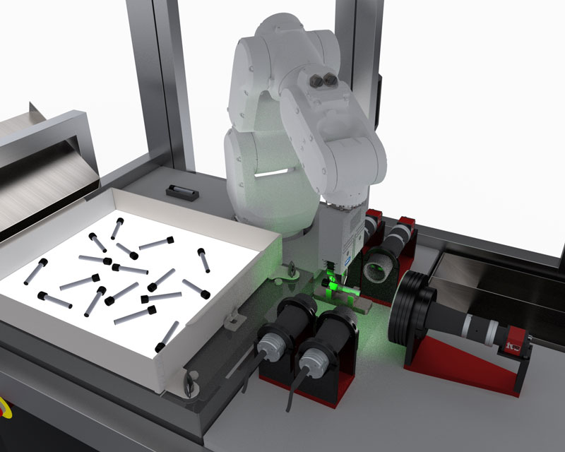
So how is machine vision used in a battery plant?

Machine vision is used in the complete electric vehicle (ev) manufacturing cycle, providing quality and consistency to the production across all areas. But getting the quality right on battery production for electric vehicles is critical for safety, life cycle and achieving greater energy density – and to prevent degradation and to minimise waste. Therefore, machine vision provides the eyes on quality in electrical vehicle manufacturing, providing 100% inspection, around the clock. From work we have done we can drill down on the 11 critical areas that machine vision is used in electric vehicle battery production for in-line quality control.

1. Coating quality inspection. During the initial coating process, linescan vision inspection is used to check for defects such as scratches, dents, dints, craters, bubbles, inclusions and holes on electrode sheets.

2. End face profile measurements. The end profiles can be continually monitored to quality assess the black electrode coating process and raise alarms in case of faults identified.

3. Coating width measurement. The anode and cathode coating has to be extremely consistent and to measurement specification. Therefore, surface inspection combined with gauging width and edge profiles helps to build up an inspection profile for the continuous coated product.

4. Electrode tab position and surface verification. During vacuum drying, a separator and electrode are brought together in cell construction. Cathode and anode cells are wrapped, rolled, or stacked together. The folded cells have lead tabs attached to them. When the cells have been loaded with electrolytes, vacuum-sealed, and dried, the procedure is complete. This process is monitored by vision inspection for anomalies and out of tolerance product. Critical to quality (CTQ) parameters are assessed in real-time.

5. Battery module defect detection. Each battery module will generally contain a number of cells (typically twelves). The modules are joined together and a cooling fluid pipe is attached. Checks for verification for module integrity, assembly characteristics and component verification are all completed using machine vision.

6. Stacking alignment and height. As modules and battery slices are built up into a complete battery pack, vision sensors measure the profile of the slice displacement and positioning to provide accurate feedback control for precision stacking.

7. Tab inspection. The tabs on the edge of each slice and subsequent modules are checked for debris, chips and cracks. Any small burr, edge deviation or dent can cause issues for the final assembled battery unit.

8. Connector Inspection. The main entry and exit to the battery module is via a high-voltage connector. The battery is charged through this connection, and electricity is delivered to the electric motor. Inspection of the main characteristics of the connector assembly are critical to provide a final check for edge deviations, male/female connector profiles and no cracks or dents in the connector profile.

9. Pouch surface inspection. Automated cosmetic inspection for inclusions, surface debris, scratches, dents and dints ensures that the lithium-ion cells are checked prior to becoming an EV battery.

10. Code reading. Codes on the battery modules need to be read for traceability and to track each element through the production process, allowing the manufacturing to trace where an EV cell is finally installed, from the individual production plant, down to the individual vehicle.

11. Final assembly verification. The final battery pack is checked for completeness to specification, all necessary assembly parts are available and verification of optical character recognition of codes for full traceability of the pack when sent to the customer for installation into the electric vehicle (EV).

For further details on IVS automotive industry solutions see: https://www.industrialvision.co.uk/industries/automotive

Robot vision trends in medical device production.

Medical device manufacturing continues to drive the adoption of robot vision to increase throughput, increase yield and reduce the reliance on manual processes. Many production facilities have now turned to collaborative robots which allow operations in medical device production to be taken to the next level of optimisation.

Cobots with vision, tend to work hand in hand with humans balancing the imperative for safety with the need for flexibility and productivity. Robots no longer need to work alone. Collaborative robots are generally designed with inherent safety so they can work alongside humans where possible. Collaborative automation means greater speed and efficiency. Of course, a thorough risk-assessment is still required but the functionality within these robots leads them to be assessed safe once the surrounding conditions and operationality capability are tuned to the safety needs (including any gripper or end-effector design).

Cobots are designed for low payload applications such as handling small parts and inspection tasks so are ideal for medical production processes. Companies continue to look for ways to improve their efficiency by using robot with vision systems, allowing automation of current manual processes to produce productivity gains. Cobots provide a lower price point and lower integration cost to the customer, providing a faster return on investment that unlocks many more industrial tasks for medical device production automation.

Some examples of the current trends in medical device manufacturing for adopting robot vision solutions include:

Machine Tending

Cobot vision removes the need for many operators to be occupied tending to production machinery, feeding and general assembly operations. The cobot can open and close a machine door, pick and place parts for assembly, and even start a machining process by pushing the start button.

Palletising

The ability to stack and un-stack pallets is another requirement, with the vision system providing real-time off-sets and alignment for the pallet stack. A compact robotic cell that accurately loads products onto a pallet, reduces the need for rework while also allowing staff to work safely around the robot. Using cobots with vision within a robot cell allows safe interaction with staff members. Personnel can enter the robot’s operational area to speed up the pallet changes, providing a robotic solution that can work around staff without risking their safety.

Box Erection

Taking flat boxes off a stack and erecting them into a useable format as outer shipper cases is a repetitive and time-consuming action in industry to which cobots with vision are very well suited. Medical device manufacturers need not only to erect the boxes and casings, but print and confirm the serial batch numbers and use by date on the product, all of which can be completed by the same machine vision inspection system.

Functional Repetitive Testing

Manufacturers need to put their products through thousands of hours of test cycling to provide reliability, for example the continued movement of a syringe body or an asthma inhaler valve. Collaborative robots with vision can performs hundreds of hours of testing to support faster testing, improving reliability and quality.

Structured Bin Picking

Parts in a structured position allowing single picks from known datums can be easily completed with cobots and smart vision sensors. Pick and place into a known fixture or position allows integration of such solutions in complex automation production processes.

Unstructured Random Bin Picking

Bin picking from a random box of parts can now be accomplished with cobots and 3D vision. A point cloud of known data, identifying individually pickable parts is fed to the robot allowing parts which would have previously required a human picker to now to picked and placed into the next process.

Robots with machine vision will continue to dominate the foreseeable needs for automation of production in medical device manufacturing. With the drive for ever greater flexibility and the need to reduce manpower and increase reliability, this area of automation will continue to be a focus for the medical devices and pharmaceutical industries.

A guide to the different lenses used in industrial vision systems.

Optical lenses are used to view objects in imaging systems. Vision system lenses are imaging components used in image processing systems to focus an image of an examined object onto a camera sensor. Depending on the lens, they can be used to remove parallax or perspective error or provide adjustable magnifications, field of views, or focal lengths. Imaging lenses allow an object to be viewed in several ways to illustrate certain features or characteristics that may be desirable in certain applications. Alongside lighting, lens selection is paramount to creating the highest level of contrast between the features of interest and the surrounding background. This is fundamental to achieving the greatest possible image quality when working with vision systems.

In this respect the lens plays an important role in gathering light from the part being inspected and projecting an image onto the camera sensor, referred to as primary magnification (PMAG). The amount of light gathered is controlled by the aperture, which is open or closed to allow more or less light into the lens and the exposure time, which determines how long the image is imposed onto the sensor.

The precision of the image depends on the relationship between the field of view (FOV) and working distance (WD) of the lens, and the number of physical pixels in the camera’s sensor.

FOV is the size of the area you want to capture.

WD is the approximate distance from the front of the camera to the part being inspected with a more exact definition taking into account the lens structure.

The focal length, a common way to specify lenses, is determined by understanding these measurements and the camera/sensor specifications.

The performance of a lens is analysed in reference to its modulation transfer function (MTF) which evaluates resolution and contrast performance at a variety of frequencies.

Types of lens

In order to achieve the highest resolution from any lens/ sensor combination the choice of the former has become an increasingly important factor in machine vision. This is because of the trend to increasingly incorporate smaller pixels on larger sensor sizes.

An ideal situation would see the creation of an individual lens working for each specific field of view, working distance and sensor combination but this highly custom approach is impractical from a cost perspective.

As a result there are a multitude of optical/lens configurations available with some of the key varieties shown below:

Lens TypeCharacteristicsApplications
Standard resolution lenses
  • sensor resolution of less than a megapixel
  • fixed focal lengths from 4.5 – 100 mm
  • MTF of 70 – 90 lp/mm
  • low distortion
  • most widely used
High resolution lenses
  • focal lengths up to 75 mm
  • MTF in excess of 120 lp/mm
  • very low distortion (<0.1%)
  • cameras with a small pixel size
  • precise measurement
Macro lenses
  • small fields of view approximately equal to camera’s sensor size
  • very good MTF characteristics
  • negligible distortion
  • lack flexibility – not possible to change iris or working distance
  • optimised for ‘close-up’ focusing
Large format lenses
  • required when camera sensor exceeds that which can be accommodated with C-mount lenses
  • often modular in construction including adapters, helical mounts and spacers
  • most commonly used in line scan applications
Telecentric lenses
  • collimated light eliminates dimensional and geometric image variations
  • no distortion
  • images with constant magnification and without perspective distortion whatever the object distance
  • to enable collimation front aperture of lens needs to be at least as large as the field of view meaning lenses for large fields of view are comparatively expensive
  • specialist metrology
Liquid lenses
  • Change shape within milliseconds
  • enables design of faster and more compact systems without complex mechanics
  • MTBF in excess of 1 billion movements
  • Longer working life due to minimal moving parts
  • where there is a need to rapidly change lens focus due to object size or distance changes
360˚
  • view every surface of object with as few cameras as possible
  • complex image shapes
360˚ – pericentric lenses
  • specific path of light rays through the lens means that a single image can show detail from the top and sides of an object simultaneously
  • cylindrical objects
360˚ – Catadioptric lenses
  • sides of inspected object observed over wide viewing angle, up to 45° at max., making it possible to inspect complex geometries under convenient perspective
  • small objects down to 7.5 mm diameter
360˚ – Hole inspection optics
  • a large viewing angle >82°
  • compatible with a wide range of object diameters and thicknesses
  • viewing objects containing holes, cavities and containers
  • imaging both the bottom of a hole and its vertical walls
360˚ – Polyview lenses
  • provide eight different views of side and top surfaces of object
  • enables inspection of object features that would otherwise be impossible to acquire with a single camera

You need enough resolution to see the defect or measure to an appropriate tolerance. Modern vision systems use sub-pixel interpolation, but nothing is better than having whole pixels available for the measurement required. Match the right lens to the right camera. If in doubt, over specify the camera resolution, most machine vision systems can cut down the image size from the sensor anyway.

The 7 elements of a machine vision system.

For today’s post we thought we’d take you back to the beginning. Not all customers have used machine vision or vision systems in their production process before, many will be new to machine vision. So it’s important to understand the basics of a vision inspection system and what the fundamentals of the overall system look like. This helps to understand how a vision inspection machine operates at a rudimentary level.

The components of a vision system include the following basic seven elements. Although each of these components serves its own individual function and can be found in many other systems, when working together they each have a distinct role to play. To work reliably and generate repeatable results it is important that these critical components interact effectively.

  • The machine vision process starts with the part or product being inspected.
  • When the part is in the correct place a sensor will trigger the acquisition of the digital image.
  • Structured lighting is used to ensure that the image captured is of optimum quality.
  • The optical lens focuses the image onto the camera sensor.
  • Depending on capabilities this digitizing sensor may perform some pre-processing to ensure the correct image features stand out
  • The image is then sent to the processor for analysis against the set of pre-programmed rules.
  • Communication devices are then used to report and trigger automatic events such as part acceptance or rejection.

It all starts with the part or product being inspected. This is because it is the part size, specified tolerances and other parameters which will help to inform the required machine vision solution. To achieve desired results the system will need to be designed so that part placement and orientation is consistent and repeatable.

A sensor, which is often optical or magnetic, is used to detect the part and trigger:

  • the light source to highlight key features and
  • the camera to capture the image

This part of the process may also include what is often referred to as ‘staging’. Imagine a theatre and this is the equivalent of putting the actor centre stage in the best possible place for the audience to see. Staging is often mechanical and is required to:

  • Ensure the correct part surface is facing the camera. This may require rotation if several surfaces need inspecting
  • Hold the part still for the moment that the camera or lens captures the image
  • Consistently put the part in the same place within the overall image ‘scene’ to make it easy for the processor to analyse.

Lighting is critical because it enables the camera to see necessary details. In fact poor lighting is one of the major causes of failure. For every application there are common lighting goals:

  • Maximising feature contrast of the part or object to be inspected
  • Minimising contrast on features not of interest
  • Removing distractions and variations to achieve consistency

In this respect the positioning and type of lighting is key to maximise contrast of features being inspected and minimise everything else.

Of course, an integrated inspection machine will have all of these aspects already designed and taken care of within the scope of the quality inspection unit, but these are some just some of the basic elements which make up the guts of a machine vision system.

Human Vision v Machine Vision (and what the operational benefits really are).

We get asked this all the time! What are the differences between using a human inspector and what can we expect from an intelligent vision system. Advances in artificial intelligence, in particular deep learning, are enabling computers to learn for themselves and so gaps in this area continue to decrease. But it’s still safe to say that vision systems work from logic, don’t get tired and don’t have an “off” day. And of course, some production processes are too high speed for an operator to inspect (such as in medical device and pharmaceutical manufacturing).

Some of the key characteristics in comparison between human and machine vision can be seen in the table below:

Human VisionMachine Vision
SpeedThe human visual system can process 10 to 12 images per second.High speed – hundreds to thousands of parts per minute (PPM)
ResolutionHigh image resolutionHigh resolution & magnification.
InterpretationComplex information. Best for qualitative interpretation of unstructured sceneFollows program precisely. Best for quantitative and numerical analysis of a structured scene
Light spectrumVisible light – Human eyes are sensitive to electromagnetic wavelengths ranging from 390 to 770 nanometres (nm) requires additional lighting to highlight parts being inspected, but can record light beyond human visible spectrum.Some machine-vision systems function at infrared (IR), ultraviolet (UV), or X-ray wavelengths.
Consistency, reliability & safetyImpaired by boredom, distraction & fatigue Continuous repeatable performance – 24/7
100% accuracy

As we can see in the table, machine vision offers some real benefits over human vision, and this is what an increasing number of industries are recognising and exploiting.

The operational benefits of machine vision

So, for the forward-thinking companies exploiting this technology, there are a number of operational benefits of machine vision including:

  • Increased competitiveness – higher productivity and output
  • Lower costs – Less downtime and waste, increased speed and error correction. Automatically identify and correct manufacturing problems on-line with machine vision forming part of the factory control network
  • Improved product quality – 100% quality check for maximum product quality
  • Improved brand reputation management – More stringent compliance with industry regulations, leading to fewer product recalls and a reduced number of complaints
  • Customer complaint handling process improvements – Image archiving and recording throughout the whole process
  • Increased safety – machine vision solutions contribute to a positive, safe working environment
  • Improvements to sustainable working practices – machine vision can improve the use of energy and resources, make material flow smoother, prevent system jams, reduce defects/waste and even save on space. It can also help to enable Just In Time processes through tracking and tracing products and components throughout the production process, avoiding component shortages, reducing inventory and shortening delivery time.
  • Higher innovation – Releasing staff from manual, repetitive tasks for higher value work can lead to greater creativity and problem-solving.

Limitations

Whilst it’s hopefully clear that there are many benefits to machine vision, there are also some limitations. Machine vision systems are able to deliver results equal to and often above human performance with greater speed, continuity and reliability over a longer time period.

However, we should remember that the way the machine ‘sees’ can only be as good as the conditions and rules that are created to enable it to do so. In this respect, it is important that the following basic rules are observed:

  • The inspection task has been described precisely and in detail, in a way appropriate for the special characteristics of machine ‘‘vision’’.
  • All permissible variants of test pieces (with regard to shape, colour, surface etc.) and all types of errors have been taken into account.
  • The environmental conditions (illumination, image capturing, mechanics etc.) have been designed in such a way that the objects or defects to be recognised stand out in an automatically identifiable way.
  • These environmental conditions are kept stable.

In a related point, machine vision can be limited by the relationship between the amount of data required to help train it and the processing power needed to efficiently process the data. However, deep learning, which enables machines to learn rather than train, requires much less data and so provides an opportunity for progress in this respect.

Why the Human Machine Interface (HMI) really does matter for vision systems.

Control systems are essential to the operation of any factory. They control how inputs from various sources interact to produce outputs, and they maintain the balance of those interactions so that everything runs smoothly. The best control systems can almost appear magical; with a few adjustments here and there, you can change the output of an entire production line without ever stopping. This is just as true for the vision inspection process and machinery.

The human machine interface (HMI) in a quality control vision system is important to provide feedback to production, monitor quality at speed and provide easy to see statistics and information. The software interface provides the operator with all information they need during production, guiding them through the process and providing instructions when needed. It also gives them access to a wide array of tools for adjusting cameras or other settings on the fly, as well as useful data such as machine performance reports.

If a product has been rejected by the inspection machine it may be some time before an operator or supervisor can review the data. If the machine is fully autonomous and communicates directly with the factory information system the data might be automatically sent to the factory servers or cloud for later recall – this is standard practice in most modern production facilities. But the inspection machine HMI can also provide an immediate ability to recall the vision image data, detailed information on the quality reject criteria and can be used to monitor shift statistics. It’s important that the HMI is clearly designed, with ergonomics and ease-of-use for the shop floor operator as the main driver. For vision systems and machine vision technology to be adopted you need the buy-in from operators, the maintenance team and line supervisors.

The layout of the operator interface is important to give immediate data and statistical information to the production team. It is important to have an interface that can be easily read from a distance, and displays the necessary information in a single screen. During high-speed inspection operations (such as medical device and pharmaceutical inspection operations) it is not possible to see every product inspected, that’s why a neatly designed vision system display, showing the last failed image, key data and statistical process control (SPC) information provides a ready interface for the operator to drill down on process specifics which may be affecting the quality of the product.

It’s clear why the HMI in quality control vision systems are so crucial to production operations. They help operators see important manufacturing inspection data when necessary, recommend adjustments on the fly, monitor production in real-time and provide useful data about performance all at once.

Top 6 medical device manufacturing defects that a vision system must reject

What does every medical device manufacturer crave? Well, the delivery of the perfect part to their pharmaceutical customer, 100% of the time. One of the major stumbling blocks to that perfect score and getting a Parts Per Million (PPM) rate down to zero are the scratches, cracks and inclusions which can appear (almost randomly) in injection moulded parts. Most of the time, the body in question is a syringe, vial, pen delivery, pipette or injectable product which is transparent or opaque in nature, which means the crack, inclusion, or scratch is even more apparent to the end customer. Here we drill down on the top six defects you can expect to see in your moulded medical device and how vision systems are used to automatically find and reject the failure before it goes out of the factory door.

1. Shorts, flash and incomplete junctions.

Some of the failures are within the tube surface and are due to a moulding fault in production. For example, incomplete injections in mouldings create a noticeable short shot in the plastic ends of the product. The forming of junctions at the bottom end of the tube creates a deformation that must be analysed and rejected. Flash is characterised as additional material which creates an out of tolerance part.

2. Scratches and weld lines

These can be present on the main body, thread area or top shaft. They often have a slight depth to them and can be evident from some angles and less so from others. These could also be confused with weld lines which can run down the shaft or body of a syringe product, but this is also a defect that is not acceptable in production.

3. Cracks

Cracks in a medical device can have severe consequences to the patient and consumer; this could allow the pharmaceutical product to leak from the device, change the dosage or provide an unclean environment for the drug delivery device. Cracks could be in the main body or sometimes in the thread area, or around the sprue.

4. Bubbles, Black Spots and Foreign Materials

Bubbles and black spots are inclusions and foreign material, which are not acceptable on any product, but on a drug delivery device that is opaque or clear in nature, they stand out a lot! These sort of particulates are typically introduced through the moulding process and need to be automatically rejected. Often, the cosmetic nature for these sorts of inclusions is more the issue than the device’s functional ability based on the reject.

5. Sink marks, depressions and distortions

Sink marks, pits, and depressions can cause distortion in the components, thus putting the device out of tolerance or off-specification from the drawing. These again are caused by the moulding process and should be automatically inspected out from the batch.

6. Chips

Chips on the device have a similar appearance to short shots but could be caused on exit from the moulding or via physical damage through movement and storage. Chips on the body can cause out of tolerance parts and potential failure of the device in use.

But how does this automatic inspection work for all the above faults?

Well, a combination of optics, lighting and filters is the trick to identifying all the defects in medical plastic products. This combined with the ability to rotate the product (if it’s cylindrical in nature) or move it in front of many camera stations. Some of the critical lighting techniques used for the automated surface inspection of medical devices are:

Absorbing – the backlight is used to create contrasts of particulates, bubbles and cosmetic defects.
Reflecting – Illumination on-axis to the products creates reflections of fragments, oils and crystallisation.
Scattering – Low angle lighting highlights defects such as cracks and glass fragments.
Polarised – Polarised light highlights fibres and impurities.

These, combined with the use of telecentric optics (an optic with no magnification or perspective distortion), allows the product to be inspected to the extremities, i.e. all the way to the top and to the bottom. Thus, the whole medical device body can be examined in one shot.

100% automated inspection has come a long way in medical device and pharmaceutical manufacturing. Utilising a precision vision system for production is now a prerequisite for all medical device manufacturers.

What are false failures in machine vision (and the art of reducing them.)

Over the last twenty plus years in the machine vision industry we’ve learnt a lot about customer expectation and the need to provide solutions which are robust, traceable and provide good value for money. One of the key elements of any installation or inspection machine is the mystical area of false failures of the vision system, and making sure this is reduced to the point of virtual elimination. A small change in the false failure rate in a positive direction can have a massive impact on yield, especially when the inspection takes place at 500 parts per minute!

For customer’s new to machine vision, it’s a concept they aren’t used to. The idea that you have to have a few false rejects events to happen in order to ensure that no false accepts take place. During the design phase of the vision set-up and inspection routine structure, we review a collection of “Good” parts as well as a pool of “Bad” parts. Statistically, this would imply an infinite number of each in order to calculate the set points for each measured feature. It is impossible to create an effective vision solution without this collection of components. We use various vision software methods to analyse all of the parts and features to create a collection of data sets using these good and bad parts.

This is where the system’s true feasibility will be determined. Once a vision tool has been created for any given feature, a population of data points will usually have some degree of uniqueness across the good and bad parts. If the data does not have two mutually exclusive distributions of results, some good parts must be rejected to ensure that no faulty parts are passed and allowed to continue to the customer. In other words, there is a cost to rejecting some good parts in order to ensure that a failed part is never sent to the customer.

You’ll notice that this chart explains the reasons for false rejections. More importantly, it emphasises that if a system is not rejecting good parts, it may be passing bad ones.

Of course, with all our years of experience in machine vision, we understand this issue – so all our systems and machines are designed so that there is enough difference between good and bad that the distributions are as distinct as possible, that’s the art. That is not so difficult to achieve in presence/absence type applications. It’s more difficult in gauging and metrology vision, where there’s some measurement uncertainty, and extremely difficult in surface flaw detection. Experience in the field of machine vision is everything when it comes to false failure reduction, and that’s what we provide you with our long-standing knowledge in vision systems.

How to run a Gauge R & R study for machine vision.

When you’re installing a vision system for a measuring task, don’t be caught out with the provider simply stating that the pixel calibration task is completed by dividing the number of pixels by the measurement value. This does provide a calibrated constant, but it’s not the whole story. There is so much more to precision gauging using machine vision. Measurement Systems Analysis (MSA) and in particular Gauge R&R studies are tests used to determine the accuracy of measurements. They are the de-facto standard in manufacturing quality control and metrology, and especially relevant for machine vision-based checking. Repeated measurements are used to determine variation and bias. Analysis of the measurement results may allow individual components of variation to be quantified. In MSA accuracy is considered to be the combination of trueness (bias) and precision (variation).

The three most crucial requirements of any vision gauging solution are repeatability, accuracy and precision. The variance of repeated measurements, or repeatability, refers to how near the measurements are to each other. The accuracy of the measurements refers to how close they are to the genuine value. The number of digits that can be read from the measurement gauge is known as precision.

A Gauge R & R (also known as Gage R & R) repeatability and reproducibility is defined as the process used to evaluate a gauging instrument’s accuracy by ensuring its measurements are repeatable and reproducible. The process includes taking a series of measurements to certify that the output is the same value as the input, and that the same measurements are obtained under the same operating conditions over a set duration.

The “repeatability” aspect of the GR&R technique is defined as the variation in measurement obtained:

– With one vision measurement system
– When used several times by the same operator
– When measuring an identical characteristic on the same part

The “reproducibility” aspect of the GR&R technique is the variation in the average of measurements made by different operators:

– Who are using the same vision inspection system
– When measuring the identical characteristic on the same part

Operator variation, or reproducibility, is estimated by determining the overall average for each appraiser and then finding the range by subtracting the smallest operator average from the largest.

So, it’s important that vision system measurements are checked against all of these aspects, so a bias test, process capability and gauge validation. The overall study should be performed as per MSA Reference Manual 2010 fourth edition.

More information on IVS gauging and measuring can be found here.

Why using vision systems to capture the cavity ID in injection moulded parts helps you stay ahead of the competition.

Machine vision systems are excellent at analysing products, capturing data and providing a large database of useful statistics for your operations and production manager to pore over. For products which are injection moulded we often get tasked with measuring key dimensions, gauging a spout or find the rogue short shot on a medical device. Normally this is at speed, with products running directly out of the Injection Moulding Machine (IMM), up a conveyor and into the vision input (normally a bowl feed, robot or conveyor), with the added bonus of images saved for reference as the automatic inspection takes place. If you’ve had a failure, it’s always a good idea to have the photo of the product to show to the quality team and for process control feedback. Let’s face it, the vision system is a goal keeper, and you need to feedback to the production team to help improve the process.

But what if the failure is intermittent and not always easy to capture? Your quality engineers may be scratching their heads, wondering why there is a product failure every now and then. Is there any way this can be tracked back to source? The neat answer is to complete cavity identification (ID) during the inspection process. The tooling for an IMM can include a cavity number so that each individual product has a unique reference. This is used for other forms of quality feedback, such as reviewing tool wear, tooling failures, short-shot imbalance and general troubleshooting for injection moulded products. So, if the cavity Identification number can be read at speed, saved and the data tracked against it, you start to see a picture of how your process is running, spikes in quality concerns related to a particular cavity, and ultimately full statistical process control of each tool cavity. Utilising precision optical character recognition allows vision systems to read each cavity number (or letter/or combination), to drill down the data to an individual cavity within the tool.

So next time the quality director comes down onto the shop floor asking what cavities are giving you problems, you’ll have all the data to hand (plus the photos to really wow them!).

Why bin picking is one of the most difficult vision system tasks (and how to overcome it!).

Autonomous bin picking, or the robotic selection of objects with random poses from a bin, is one of the most common robotic tasks, but it also poses some of the most difficult technological challenges. To be able to localise each part in a bin, navigate to it without colliding with its environment or other parts, pick it, and safely place it in another location in an aligned position – a robot must be equipped with exceptional vision and robotic intelligence.

Normally the 3D vision system scanner is mounted in a fixed, stationary position in the robotic cell, usually above and in-line with the bin. The scanner must not be moved in relation to the robot after the system has been calibrated. As a general rule of thumb, the more room is required for the bin picking application – including the space for robot movement, the size of the bin and parts, etc. – the larger model of the machine vision scanner required. So more resolution and pixels equates in simple terms to more precision and accuracy.

Calibration is completed with any suitable ball attached to the endpoint of the robotic arm or to the gripper. The ball needs to be made of a material that is appropriate for scanning, which means it needs to be smooth and not too reflective.

One of the problems with this approach is that the 3D vision system itself could cast a shadow on the bin and inhibit a high-quality acquisition of the scene. This problem is usually solved by making a compromise and finding the most optimal position for the scanner in relation to the bin or by manually rearranging the parts within the bin so that the vision system captures them all in the end. But is there another way?

A way to overcome this is to mount the 3D vision system on the robot itself. Of course, there are certain prerequisites to this approach (i.e. the robot can cope with the additional weight, there is room for mounting and there is cycle time available for movement), but there is some functional advantages to this approach.

For a successful calibration, the scanner must be mounted behind the very last joint (e.g. on the gripper). Any changes made to the scanner’s position after the calibration renders the calibration matrix invalid and the whole calibration procedure must be carried out again. This sort of calibration is done with a marker pattern – a flat sheet of paper (or another material) with a special pattern recognized the 3D vision system.

So what are the advantages? Well, you can’t scan your large bin with a smaller (and so lower cost) vision system scanner, because your scanner is mounted above it and its view is fixed. A small scanner mounted directly on the robotic arm allows you to get closer to the bin and choose which part of it to scan, thus potentially saving costs and helping with resolution.

Robotic mounted bin picking may also eradicate the need to darken the room where the robotic cell is located. The ambient light coming from a skylight might pose serious challenges to the deployed 3D vision system. A scanner attached to the robot can make scans of a bin from one side first and then from another, minimising the need to make any unusual adjustments to the environment.

It can also happen that the 3D vision system itself casts shadows on the bin and inhibits a high-quality acquisition of the scene. This problem is usually solved by making a compromise and finding the most optimal position for the scanner in relation to the bin or by manually rearranging the parts within the bin so that the vision system captures them all in the end. Robot mounted picking eliminates this problem as it enables the scanner to “look” at the scene from any angle and from any position.

In conclusion, there are many approaches to automated bin picking using 3D vision systems, each with their own unique approaches dependent on the environment, industrial automation needs, cost and the cycle time available for picking.

INDUSTRIAL VISION SYSTEMS LAUNCHES OPTICAL SORTING MACHINES TO DRIVE EFFICIENCY AND MINIMISE WASTE

Industrial Vision Systems (IVS), a supplier of inspection machines to industry, has launched a range of new optical sorting machines specifically for the high-speed sorting of small components such as fasteners, rings, plastic parts, washers, nuts, munitions and micro components. The devices provide automatic inspection, sorting, grading and classification of products at up to 600 parts per minute. The systems intercept and reject failed parts at high speed, discovering shifts in quality, and providing quality assurance through the production cycle.

The new Optical Sorting Machines from IVS utilise the latest vision inspection algorithms allowing manufacturers to focus on other activities while the fully automated sorting machines root out rogue products and make decisions on quality automatically. For classification checks, the systems use Artificial Intelligence (AI) and Deep Learning, providing the machines with an ability to “learn by example” and improve as more data is captured.

The glass disc of the machine provides 360-degree inspection enabling the system to act as the ‘eyes’ on the factory floor and record production trends and data. By intercepting and rejecting failed parts at high speed, it gives manufacturers the ability to provide 100% automatically inspected product to their customers, without human intervention.

With real-time data and comprehensive reporting to see defect rates, this enables engineers to immediately respond to problems and take corrective action before products are delivered to a customer.

Andrew Waller, director at Industrial Vision Systems, said: “Our machines allow manufacturers to stay ahead of their competitors. These new systems are designed for manufacturers of mass-produced, small products which previously would have struggled to sort quality concerns. We can perceive and detect defects others miss at high-speed. Our optical sorting technology takes vision inspection to the next level. Clear, ultra-high-definition images allow our new generation of systems to recognise even the hardest to spot flaws and to sort wrong batch parts. This allows our customers to achieve continuous yield reductions, categorise failures based on their attributes, and build better products.”